Setup
First Time Setup
Before being able to properly take data on a new module, there are a number of
parameters which need to be properly configured, which can be done using the
uxm_setup and uxm_relock modules in sodetlib.
For first time setup, many of these parameters must be computed, and a tunefile
must be made from scratch. The uxm_setup operation goes through the
procedures described below to figure out these initial values. Operating
parameters are all stored in the Device Config, so this really only needs to be
run once per cooldown / module. If this has already been done, you can use the
Relocking function to return to a functioning state based on params already
stored in the device cfg.
To run the setup procedure, you can simply run
from sodetlib.operations.uxm_setup import uxm_setup

success, summary = uxm_setup(S, cfg, bands=np.arange(8))
The setup procedures take many input configuration parameters from the device cfg, so to modify these you’ll either want to edit the dev cfg file or modify the cfg object before passing it to the setup function, for example
from sodetlib.operations.uxm_setup import uxm_setup

# Increases the amp drain current tolerance to 0.5 mA
cfg.dev.exp['amp_hemt_Id_tolerance'] = 0.5
success, summary = uxm_setup(S, cfg, bands=np.arange(8))
Amplifier Setup
First we must bias the cold 50k and hemt amplifiers. Depending on the cryocard revision, either one set (C02) or two sets (C04/C05) of amplifiers can be biased via smurf. Additionally, the C04/C05 cryocards allow the drain voltages to be specified, while for C02 cryocards these are fixed.
The setup_amps function will first determine which revision cryocard is
connected based on firmware version, and therefore which amplifiers are able
to be biased. To be biased, these amps must also be listed in the device cfg.
It then enables the amps / sets the drain voltages if necessary.
It then checks if the amps happen to already be
biased properly. If not, the function will sweep the gate-voltage until it
finds one that hits the target drain voltages specified in the device cfg.
Attenuator Estimation
In order for phase-delay-estimation and resonator tuning to work properly, the power going into the smurf has to be balanced such that it doesn’t saturate the ADC’s, but still is large enough for the peak-finding algorithms to work. Two modifiable attenuators per-band can be used to determine the power loss between the smurf-output and the cryostat-input (the UC attenuation) and the between the cryostat-output and smurf-input (the DC attenuation).
We can sweep over these parameters to determine what they should be to achieve optimal noise, but for the time being we just want to estimate what the attens should be in order to properly run estimate-phase-delay and the tuning procedure.
For this step, we want to find the value att for each band such that when
we set both the UC and DC atten to att we get a reasonable amplitude
response. To do this we start at att=15, and perform a binary search to
find a value of att that puts us in the correct power region.
Estimate Phase Delay
Estimate Phase Delay is run for each band to measure the analog and digital phase delay for each band. See the pysmurf docstrings for more detail.
Initial Tune
To tune from scratch, we run the following pysmurf functions for each smurf-band:
First we run find_freq, which does a course sweep of the frequency range of the smurf-band, and finds approximate peak locations. The
res_amp_cutandres_grad_cutoptions can be modified in the device cfg to change the threshold of which peaks are cut.Then we run
setup_notches, which takes a fine scan across each resonance in series, obtaining a better estimate of the peak frequency. This takes a longer time, and will take roughly 45 min to run on all 8 bands.Finally we run the
run_serial_gradient_descentandserial_eta_scanfunctions to further hone in on resonances, and to calculate the eta param for each channel.
After this procedure you end up with a populated tunefile containing the resonance frequencies and eta parameters for each resonator. This is stored in the device cfg and will be used whenever you have to relock detectors.
Tracking
Next we run the tracking setup procedures (See the Tracking section).
Noise
Finally we are able to take detector data! We take a 30 second timestream here and calculate the white noise levels for all channels.
The detectors at this point are superconducting, so the white noise is given by:
with
Here you want to plug in values for your bath temperature and shunt resistances to see if the median white noise levels make sense. For example, with \(T_b = 100 \; \mathrm{mK}\) and \(R_\mathrm{sh} = 0.4 \; \mathrm{m}\Omega\), you can expect a white noise level of around \(125 \; \mathrm{pA}/\sqrt{\mathrm{Hz}}\). If you’re close to this number, you’re good to go and ready to continue with taking a biasgroup map!
If you’re seeing white noise levels much higher than this, something is probably wrong and you may need to go back and run the previous steps individually to debug (see the API section for how to run each step individually).
API
- sodetlib.operations.uxm_setup.estimate_uc_dc_atten(S, cfg, band, update_cfg=True, tone_power=None)
Provides an initial estimation of uc and dc attenuation for a band in order to get the band response at a particular frequency to be within a certain range. The goal of this function is to choose attenuations such that the ADC isn’t saturated, and the response is large enough to find resonators.
For simplicity, this searches over the parameter space where uc and dc attens are equal, instead of searching over the full 2d space.
For further optimization of attens with respect to median white noise, run the
optimize_attensfunction from thesodetlib/operations/optimize.pymodule.The following parameters can be modified in the device cfg:
- bands:
tone_power (int): Tone power to use for atten estimation
- Parameters:
S (SmurfControl) – Pysmurf instance
band (int) – Band to estimate attens for
update_cfg (bool) – If true, will update the device cfg and save the file.
- sodetlib.operations.uxm_setup.find_drain_voltage(S, target_Id, amp_name, vd_min=0.1, vd_max=0.95, max_iter=50, wait_time=0.5, id_tolerance=0.2)
Scans through bias voltage for hemt amplifier to get the correct drain voltage for a target current.
- Parameters:
S (pysmurf.client.SmurfControl) – PySmurf control object
target_Id (float) – Target amplifier current
vd_min (float) – Minimum allowable drain voltage
vd_max (float) – Maximum allowable drain voltage
amp_name (str) – Name of amplifier. Must be one of [‘hemt’, ‘hemt1’, ‘hemt2’].
max_iter (int, optional) – Maximum number of iterations to find voltage. Defaults to 30.
wait_time (float) – Time to wait after setting the voltage at each step. Defaults to 0.5 sec
id_tolerance (float) – Max difference between target drain current and actual drain currents for this to be considered success (mA). Defaults to 0.2 mA.
- Returns:
success – Returns a boolean signaling whether voltage scan has been successful. The set voltages can be read with S.get_amplifier_biases().
- Return type:
bool
- sodetlib.operations.uxm_setup.find_gate_voltage(S, target_Id, amp_name, vg_min=-2.0, vg_max=0, max_iter=50, wait_time=0.5, id_tolerance=0.2)
Scans through bias voltage for hemt or 50K amplifier to get the correct gate voltage for a target current.
- Parameters:
S (pysmurf.client.SmurfControl) – PySmurf control object
target_Id (float) – Target amplifier current
vg_min (float) – Minimum allowable gate voltage
vg_max (float) – Maximum allowable gate voltage
amp_name (str) – Name of amplifier. Must be one of [‘hemt’, ‘hemt1’, ‘hemt2’, ‘50k’, ‘50k1’, ‘50k2’].
max_iter (int, optional) – Maximum number of iterations to find voltage. Defaults to 30.
wait_time (float) – Time to wait after setting the voltage at each step. Defaults to 0.5 sec
id_tolerance (float) – Max difference between target drain current and actual drain currents for this to be considered success (mA). Defaults to 0.2 mA.
- Returns:
success – Returns a boolean signaling whether voltage scan has been successful. The set voltages can be read with S.get_amplifier_biases().
- Return type:
bool
- sodetlib.operations.uxm_setup.setup_amps(S, cfg, update_cfg=True, enable_300K_LNA=True, max_attempts=3)
Initial setup for 50k and hemt amplifiers. For C04/C05 cryocards, will first check if the drain voltages are set. Then checks if drain currents are in range, and if not will scan gate voltage to find one that hits the target current. Will update the device cfg if successful. If connected to an ASU hemt (as determined by cfg values), this will scan drain voltage instead of gate voltage.
The following parameters can be modified in the device cfg, where {amp} is one of [‘hemt’, ‘hemt1’, ‘hemt2’, ‘50k’, ‘50k1’, ‘50k2’]:
- exp:
amp_enable_wait_time (float): Seconds to wait after enabling amps before scanning gate voltages
amp_{amp}_drain_current (float): Target drain current (mA)
amp_{amp}_drain_current_tolerance (float): Tolerance for drain current (mA)
amp_{amp}_drain_volt (float) : Drain voltage (V). C04/C05 cryocards only.
amp_{amp}_gate_volt_{min, max} : Limits on gate voltage (V).
- Parameters:
S (SmurfControl) – Pysmurf instance
cfg (DetConfig) – DetConfig instance
update_cfg (bool) – If true, will update the device cfg and save the file.
enable_300K_LNA – If true, will turn on the 300K LNAs.
max_attempts (int) – Maximum number of attempts at reading amplifier biases, which sometimes fails
- sodetlib.operations.uxm_setup.setup_fixed_tones(S, cfg, bands=None, fixed_tones_per_band=8, min_gap=10, tone_power=10, update_cfg=True)
Identify gaps between resonators and attempt to place a number of fixed tones there. These will be saved for every band in the device config. A tune should be available before running this action.
- Parameters:
S (SmurfControl) – Pysmurf instance
cfg (DetConfig) – DetConfig instance
bands (list of int) – The bands to set fixed tones in. Get from config by default.
fixed_tones_per_band (int) – The number of tones to place in each band. Defaults to 8.
min_gap (float) – The minimum gap size in order to place a fixed tone, in MHz. Defaults to 10.
tone_power (int) – The tone power to use for the fixed tones. Defaults to 10.
update_cfg (bool) – Whether to save the fixed tone configuration to the device config. Defaults to True.
- Returns:
fixed_tones – Fixed tones configuration, as saved to device config.
- Return type:
dict
- sodetlib.operations.uxm_setup.setup_phase_delay(S, cfg, bands, update_cfg=True)
Runs estimate phase delay and updates the device cfg with the results. This will run with the current set of attenuation values.
- Parameters:
S (SmurfControl) – Pysmurf instance
cfg (DetConfig) – DetConfig instance
uc_att (int) – UC atten to use for phase-delay estimation
dc_att (int) – DC atten to use for phase-delay estimation
update_cfg (bool) – If true, will update the device cfg and save the file.
- sodetlib.operations.uxm_setup.setup_tune(S, cfg, bands, show_plots=False, update_cfg=True)
Find freq, setup notches, and serial gradient descent and eta scan. Also sets up fixed tones, but does not turn them on.
The following parameters can be modified in the device cfg:
- exp:
res_amp_cut (float): Amplitude cut for peak-finding in find-freq
res_grad_cut (float): Gradient cut for peak-finding in find-freq
- bands:
tone_power (int): Tone power to use for atten estimation
- Parameters:
S (SmurfControl) – Pysmurf instance
cfg (DetConfig) – DetConfig instance
show_plots (bool) – If true, will show find_freq plots. Defaults to False
update_cfg (bool) – If true, will update the device cfg and save the file.
- sodetlib.operations.uxm_setup.turn_off_fixed_tones(S, cfg, bands=None)
Read fixed tones from the device config and set their amplitude to 0.
- Parameters:
S (SmurfControl) – Pysmurf instance
cfg (DetConfig) – DetConfig instance
bands (list of int) – The bands to operate on. Get from config by default.
- sodetlib.operations.uxm_setup.turn_on_fixed_tones(S, cfg, bands=None)
Read fixed tones from the device config and ensure the corresponding channels are set to the specified amplitude and have feedback disabled.
- Parameters:
S (SmurfControl) – Pysmurf instance
cfg (DetConfig) – DetConfig instance
bands (list of int) – The bands to operate on. Get from config by default.
- sodetlib.operations.uxm_setup.uxm_setup(S, cfg, bands=None, show_plots=True, update_cfg=True, modify_attens=True, skip_phase_delay=False, skip_setup_amps=False)
The goal of this function is to do a pysmurf setup completely from scratch, meaning no parameters will be pulled from the device cfg.
The following steps will be run:
setup amps
Estimate phase delay
Setup tune
setup tracking
Measure noise
The following device cfg parameters can be changed to modify behavior:
- exp:
downsample_factor (int): Downsample factor to use
coupling_mode (str): Determines whether to run in DC or AC mode. Can be ‘dc’ or ‘ac’.
synthesis_scale (int): Synthesis scale to use
amp_enable_wait_time (float): Seconds to wait after enabling amps before scanning gate voltages
amp_hemt_Id (float): Target drain current for hemt amp (mA)
amp_50k_Id (float): Target drain current for 50k amp (mA)
amp_hemt_Id_tolerance (float): Tolerance for hemt drain current (mA)
amp_50k_Id_tolerance (float): Tolerance for 50k drain current (mA)
res_amp_cut (float): Amplitude cut for peak-finding in find-freq
res_grad_cut (float): Gradient cut for peak-finding in find-freq
- bands:
tone_power (int): Tone power to use for atten estimation
- Parameters:
S (SmurfControl) – Pysmurf instance
cfg (DetConfig) – DetConfig instance
show_plots (bool) – If true, will show find_freq plots. Defaults to False
update_cfg (bool) – If true, will update the device cfg and save the file.
modify_attens (bool) – If true or attenuations are not set in the device config, will run estimate_uc_dc_atten to find a set of attenuations that will work for estimate_phase_delay and find_freq. If False and attenuation values already exist in the device config, this will use those values.
skip_phase_delay (bool) – If True, will skip the estimate_phase_delay step
skip_setup_amps (bool) – If True, will skip amplifier setup
Relocking
When resetting a system using an existing tune, we use the uxm_relock
function, which uses existing device cfg parameters to get you into the state
where you’re ready to take data. This is much faster because generally you
don’t need to estimate attens, run setup notches, or figure out the tracking
parameters for each band.
Other than that, the relock procedure is similar to the setup procedure described above:
First amplifiers are setup using the same function
Then the tunefile in the device cfg is loaded and we enable them with
relockorsetup_notches, and run the serial gradient descent and eta scan functions.Then we run
tracking_setupbased on parameters stored in the device cfg.Finally we take a noise timestream to verify that things are set up properly
To do this you can use the uxm_relock function
from sodetlib.operations.uxm_relock import uxm_relock

success, summary = uxm_relock(S, cfg, bands=np.arange(8))
If band-medians give reasonable results (see the Noise section above) you’re good to go!
Note that if setup_notches is run, a new tracking file will be created,
and if new_master_assignment is set to True, there is a small possibility
that the smurf channel assignments are not the same as the previous tune.
If this is the case, you will probably want to retake a bgmap and an IV to get
data that corresponds to the current channel assignment.
API
- sodetlib.operations.uxm_relock.get_full_band_sweep(S, cfg, band, chan)
This runs full_band_ampl_sweep to get the resonator response around a single channel. This is useful for debugging bad channels.
- Parameters:
S (SmurfControl) – Pysmurf instance
cfg (DetConfig) – Det Config instance
band (int) – smurf-band of channel
channel (int) – smurf-channel of channel
- Returns:
fs (np.ndarray) – Array of frequencies that were swept over
resp (np.ndarray) – Complex transmission across the frequency range
- sodetlib.operations.uxm_relock.plot_channel_resonance(S, cfg, band, chan)
Measures and plots resonator properties for a single smurf channel. This will perform a scan around the specified channel, and will plot the resonance dip along with where smurf thinks the resonance frequency is. This is very useful for debugging why a channel isn’t reading out properly.
- Parameters:
S ((SmurfControl)) – pysmurf instance
cfg ((DetConfig)) – DetConfig instance
band ((int)) – smurf band number
chan ((int)) – smurf channel number
- sodetlib.operations.uxm_relock.reload_tune(S, cfg, bands, setup_notches=False, new_master_assignment=False, tunefile=None, update_cfg=True)
Reloads an existing tune, runs setup-notches and serial grad descent and eta scan.
- Parameters:
S (SmurfControl) – Pysmurf instance
cfg (DetConfig) – Det config instance
bands (list, optional) – List of bands to run
setup_notches (bool) – Whether to run setup_notches
new_master_assignment (bool) – Whether to create a new master assignment
tunefile (str) – Tunefile to load. Defaults to the tunefile in the device cfg.
update_cfg (bool) – If true, will update the device cfg with the tunefile created by setup notches.
- sodetlib.operations.uxm_relock.run_grad_descent_and_eta_scan(S, cfg, bands=None, update_tune=False, force_run=False, max_iters=None, gain=None)
This function runs serial gradient and eta scan for each band. Critically, it pulls in gradient descent tune parameters from the device config and uses them to setup the grad descent operation before running.
- Parameters:
S (SmurfControl) – Pysmurf instance
cfg (DetConfig) – Det config instance
bands (list, optional) – List of bands to run on. Defaults to all 8
update_tune (bool) – If this is set to True, the new resonance frequency and eta parameters will be loaded into the smurf tune, and a new tunefile will be written based on the new measurements.
force_run (bool) – If True, will reset the
etaScanInProgressvariable to force it to re-run. This might be necessary if serial gradient descent failed out.
- sodetlib.operations.uxm_relock.uxm_relock(S, cfg, bands=None, show_plots=False, setup_notches=False, new_master_assignment=False, reset_rate_khz=None, nphi0=None, skip_setup_amps=False)
Relocks resonators by running the following steps:
Reset state (all off, disable waveform, etc.)
Set amps and check tolerance
load tune, setup_notches, serial grad descent and eta scan
Tracking setup
Measure noise
- Parameters:
S (SmurfControl) – Pysmurf instance
cfg (DetConfig) – Det config instance
bands (list, optional) – List of bands to run on. Defaults to all 8
setup_notches (bool) – If True, will run setup notches instead of relocking
new_master_assignment (bool) – Whether to run setup_notches with new_master_assignment. Defaults to False
reset_rate_khz (float, optional) – Flux Ramp Reset Rate to set (kHz), defaults to the value in the dev cfg
nphi0 (int, optional) – Number of phi0’s to ramp through. Defaults to the value that was used during setup.
show_plots (bool) – If True will show plots
skip_setup_amps (bool) – If True will skip amplifier setup.
- Returns:
summary – Dictionary containing a summary of all run operations.
- Return type:
dict
Tracking
When we run setup_tracking we are configuring variables that SMuRF uses to
track resonators and extract the TES current. This is an essential part of the
setup procedure, and a common place for things to go wrong.
When setting up tracking, we are setting three main parameters:
The frequency of the flux-ramp wave (
reset_rate_khz)The amplitude of the flux-ramp wave (as a fraction of the max value output by the DAC:
frac_pp)The squid modulation frequency being tracked by smurf for each band
lms_freq.
Setup Tracking Params
The setup_tracking_params function will pull the desired flux-ramp freq
and \(N \Phi_0\) (the number of squid-curve periods desired for each
channel) and calculate the optimal flux-ramp amplitude for each individual
band.
Tracking parameters can be configured through the device cfg object (see
setup_tracking_params docstring for more details). For instance, if you
want to change the fraction full scale used to perform the initial lms_freq
estimation, you can run
from sodetlib.operations import tracking

bands = np.arange(8)
cfg.dev.exp['init_frac_pp'] = 0.45
res = tracking.setup_tracking_params(S, cfg, bands)
Relock Tracking Setup
Once optimal tracking params have been determined for each band individually, these can be used to compute the tracking parameters that should be used if you want to run with a combination of bands, or if you want to run at other flux-ramp frequencies or \(N \Phi_0\) values.
For instance, the following block will set up tracking using the optimal parameters for band 0:
from sodetlib.operations import tracking

bands = [0]
res = tracking.relock_tracking_setup(S, cfg, bands)
And this will set up tracking for all bands running with a flux-ramp rate of 20 kHz and \(N \Phi_0 = 1\)
from sodetlib.operations import tracking

bands = np.arange(8)
res = tracking.relock_tracking_setup(
    S, cfg, bands, reset_rate_khz=20, nphi0=1
)
Tracking Results and Cutting Channels
Both setup_tracking_params and relock_tracking_setup save and return a
TrackingResults object, which contains the tracking data for all channels
on the specified bands. Along with the actual tracked-freq f and freq-error
df for every channel, this will contain the peak-to-peak amplitude of f
and df, and the tracking-quality value r2. The “tracking quality” is
the r-squared value between the measured freq response, and the average freq
response across all flux-ramp resets, giving a measure on how regular the
tracking response is over time. These values are used to determine which
channels are good and which should be cut.
To view the summary plot corresponding to a results object, you can run:
from sodetlib.operations import tracking

bands = np.arange(8)
res = tracking.relock_tracking_setup(
    S, cfg, bands, reset_rate_khz=20, nphi0=1
)
tracking.plot_tracking_summary(res)
which will produce a plot like this:
If most of the points in are blue and centered around the green region,
everything’s probably working properly! The f_ptp_range,
df_ptp_range, and r2_min keys in the device cfg can be modified to
adjust what channels are accepted.
To investigate the behavior of an individual channel, you can run:
band, channel = 0, 10
idx = np.where(
    (res.bands == band) & (res.channels == channel)
)[0][0]
tracking.plot_tracking_channel(res, idx)
which will produce the plot below.
Disabling Bad Channels
To turn off the “bad channels” determined by the tracking results object
you can use the disable_bad_chans function:
from sodetlib.operations import tracking

bands = np.arange(8)
res = tracking.relock_tracking_setup(
    S, cfg, bands, reset_rate_khz=20, nphi0=1
)

tracking.disable_bad_chans(S, res)
API
- class sodetlib.operations.tracking.TrackingResults(*args, **kwargs)
Class for storing, saving, and interpreting results from tracking_setup. This class can store tracking results for multiple bands at a time. When created, all results array are initialized to be empty. To add results from individual bands one at a time, use the
add_band_datafunction.- Parameters:
S (SmurfControl) – Pysmurf Instance
cfg (DetConfig) – DetConfig
- meta
Metadata dictionary
- Type:
dict
- f_ptp_range
Array of len(2) containing the min and max allowed f_ptp. This will be pulled from the dev cfg.
- Type:
np.ndarray
- df_ptp_range
Array of len(2) containing the min and max allowed df_ptp. This will be pulled from the dev cfg.
- Type:
np.ndarray
- r2_min
Min value of r2 for a channel to be considered good
- Type:
float
- bands
Array of len (nchans) containing the band of each channel
- Type:
np.ndarray
- channels
Array of shape (nchans) containing the smurf-channel of each channel
- Type:
np.ndarray
- f
Array of shape (nchans, nsamps) containing the tracked freq response (kHz) throughout the tracking setup call
- Type:
np.ndarray
- df
Array of shape (nchans, nsamps) containing the untracked freq response (kHz) throughout the tracking setup call
- Type:
np.ndarray
- sync_idx
Array of shape (nchans, num_fr_periods) containing the indices where the flux ramp resetted
- Type:
np.ndarray
- r2
Array of shape (nchans) containing the r-squared value computed by tracking-quality for each channel
- Type:
np.ndarray
- f_ptp
Array of shape (nchans) containing the f_ptp of each channel
- Type:
np.ndarray
- df_ptp
Array of shape (nchans) containing the df_ptp of each channel
- Type:
np.ndarray
- is_good
Array of shape (nchans) containing True if the channel passes cuts and False otherwise
- Type:
np.ndarray
- add_band_data(band, f, df, sync, tracking_kwargs=None)
Computes tracking-related data based on the tracking response, and updates the arrays described in the attributes with channels from a new band
- Parameters:
band (int) – Band of the data you’re adding
f (np.ndarray) – Tracked freq response as returned by tracking_setup
df (np.ndarray) – Untracked freq response as returned by tracking_setup
sync (np.ndarray) – sync arrayas returned by tracking_setup
- find_bad_chans(f_ptp_range=None, df_ptp_range=None, r2_min=None)
Recomputes the
is_goodarray based on cuts ranges.
- sodetlib.operations.tracking.compute_tracking_quality(S, f, df, sync)
Computes the tracking quality parameter from tracking_setup results. Tracking quality is a measure of how periodic the tracking response is with respect to the flux-ramp. It is defined as the r-squared value between the measured frequency response (f+df), and the (f+df) response averaged across all flux-ramp periods. If the signal is regular with respect to flux-ramp, the true freq response will be similar to the average freq response, resulting in a high r-squared value. If the signal is irregular, the true and average freq response will differ, resulting in a lower r-squared value. This can be used in conjunction with the f and df peak-to-peak values to determine which channels are tracking correctly.
- Parameters:
S (SmurfControl) – Pysmurf instance
f (np.ndarray) – Array of the tracked frequency for each channelk (kHz), as returned by tracking_setup
df (np.ndarray) – Array of the tracked frequency error for each channel (kHz), as returned by tracking_setup
sync (np.ndarray) – Array containing tracking sync flags, as returned by tracking_setup
- sodetlib.operations.tracking.disable_bad_chans(S, tr, bands=None, **kwargs)
Disables cut channels based on a TrackingResults object.
- sodetlib.operations.tracking.plot_tracking_channel(tr, idx, show_text=True)
Plots single tracking channel from results
- sodetlib.operations.tracking.plot_tracking_summary(tr)
Plots summary of tracking results
- sodetlib.operations.tracking.relock_tracking_setup(S, cfg, bands=None, reset_rate_khz=None, nphi0=None, feedback_gain=None, lms_gain=None, show_plots=False, frac_pp=None)
Sets up tracking for smurf. This assumes you already have optimized lms_freq and frac-pp for each bands in the device config. This function will chose the flux-ramp fraction-full-scale by averaging the optimized fractions across the bands you’re running on.
This function also allows you to set reset_rate_khz and nphi0. The fraction-full-scale, and lms frequencies of each band will be automatically adjusted based on their pre-existing optimized values.
Additional keyword args specified will be passed to S.tracking_setup.
- Parameters:
S (SmurfControl) – Pysmurf instance
cfg (DetConfig) – Det config instance
reset_rate_khz (float, optional) – Flux Ramp Reset Rate to set (kHz), defaults to the value in the dev cfg
nphi0 (int, optional) – Number of phi0’s to ramp through. Defaults to the value that was used during setup.
disable_bad_chans (bool) – If true, will disable tones for bad-tracking channels
- Returns:
res – Dictionary of results of all tracking-setup calls, with the bands number as key.
- Return type:
dict
- sodetlib.operations.tracking.setup_tracking_params(S, cfg, bands, update_cfg=True, show_plots=False)
Sets up tracking parameters by determining correct frac-pp and lms-freq for each band.
- Parameters:
S (SmurfControl) – Pysmurf instance
cfg (DetConfig) – DetConfig instance
bands (np.ndarray, int) – Band or list of bands to run on
update_cfg (bool) – If true, will update the device cfg and save the file.
show_plots (bool) – If true, will show summary plots
Debugging Issues
There are many issues that result in failure somewhere in the setup or relock procedure, including:
Amplifiers not functioning properly
Flux-ramp not being received by the UFM
SMuRF’s resonance center frequency is off of the true resonance frequency
SMuRF’s eta estimation is off
Phase-delay estimation is off
Any of these may result in bad tracking performance and high noise levels.
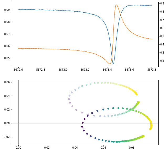
In order to debug, it is extremely useful to visualize the resonator response
and how SMuRF is tracking it. The plot_channel_resonance function in the
uxm_relock package will allow you to view a single resonator, by scanning
the probe-tone across the subband (much like setup-notches but for a single
channel).
The plot below shows a relatively well-behaved resonator. The SMuRF central frequency (the dashed vertical line) sits approximately at the resonance minimum, and the eta circle in the bottom plot is properly rotated so that it sits on the positive x-axis.
The two plots below show resonators which are not functioning properly. The plot to the left shows a resonator where SMuRF’s central resonance frequency sits far from the resonance minimum. This might be due to TES bias conditions being different than they were when the tune was taken, causing there to be a different amount of flux through the SQUID.
The plot on the right shows a large linear slope in the phase of the transmitted signal, indicative of the phase-delay not being set correctly. This might be fixed by re-running estimate phase delay.

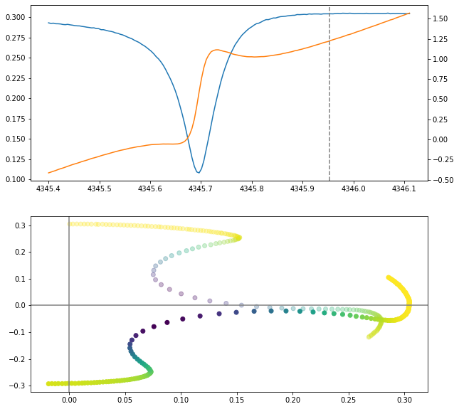
If the amplitude of the transmitted signal is an order of magnitude lower than those shown here, it indicates that amplifiers might not be on or functioning properly.
If the resonator looks good but is still not seeing any signal during tracking (with tracking-feedback off) it is likely that the flux-ramp signal is not making it to the detector.